
I have been working on a Solidworks 3D CAD model of the original Gold Tub RC10 as shown above. The end goal is to design a tube chassis for the RC10 parts which will replace the tub chassis for a more realistic look. This was done back in the 80’s by a company called Real Racing. I will be making a few modifications to the original design to improve fit and appearance, but overall it will be the same. There are a few flat body panels that go on the car, but they’re not in this photo. This is a photo of an original Real Racing Chassis.

With Solidworks 3D models of the original RC10 parts, the possibilities are endless. I can have parts made to replace the originals which were discontinued nearly 20 years ago. I can also create aluminum parts easily and precisely. This is the same software Team Associated has been using for several years. Their manuals are Solidworks drawings with notations. That’s why they look so 3D and real.
All of my measurements are being done to 3 decimal places of an inch (.xxx) and are measured several times before using them in the drawings. Hopefully this will be sufficient for proper fit if I were to have them manufactured, but the main goal here is to have a 3D model close enough to the real thing that I can design my roll cage and ensure it fits perfectly around the rest of the car.
Click on any image to enlarge


The 6-Gear Tranny is a simple block drawing to get the fit right. I almost went into great detail on it and built the whole thing, but that’s not what this project is about.


The chassis is coming along nicely, but some measurements are yet to be fully defined. The rear plate will be adjusted as will the overall wheelbase. It is surprisingly easy to make changes to the chassis and I might make some minor tweaks to its shape later on. The crossmembers are sketched in and will be moved for the final drawing.
I plan to add holes in the rear plate to allow using the Stealth tranny. Right now it’s only designed for the 6-Gear tranny.


This is the motor plate. It was the hardest part to model because of the arcs and holes. It is very difficult to just measure this piece and recreate it in a CAD program. But, it’s nearly perfect now.


These are the original RC10 shock towers, or shock struts as the manual refers to them. Both of these have been discontinued by Associated, so my drawings will come in handy if I want to make some for my models.
My next step will be to assemble these parts in Solidworks so I can start drawing the tube chassis. This will allow me to make sure parts don’t interfere with the chassis. It looks like I won’t have to draw every single part of the car to make the chassis fit properly. Here are a couple shots with some of the parts assembled and the chassis taking shape.


When I get a few of these ready, I will be either painting or powdercoating them and making some nice body panels out of then R/C car body plastic. This is actually Lexan or polycarbonate and I plan on using .030″ or thicker material for a pretty durable body.
UPDATE 5-30-2009
I just received my new Miller 150 TIG welder and plenty of Argon to get started on the welding phase of this project. Now I need a workshop, coming in July, and some metal to use for a welding bench.
UPDATE 3-7-2010
Well, the workshop is built and just needs a workbench and a number of other things to get it ready. Right now it’s just an empty room inside a 24’x44′ garage, so there’s a lot of work yet to do. I underestimated how much work this would be and it has really set this chassis project back a while.
I am not estimating when anything will be done on this project right now, but can tell you the next steps. First, I need to make a simple jig to test the bends. When bending tubing, the jig needs to let it bend a little bit further than the desired final bend. This is because the tube will spring a little bit. I need to correctly figure out this spring factor to build an accurate jig system.
I also plan to practice fitup and welding of various joints so I can see what prep work will be needed. I am hoping that I can fill in pretty good gaps and make the welds smooth. I am an excellent welder, but do not normally work on stuff this small without a foot pedal welder. I think my welder will work with a foot pedal, and this might be necessary to achieve the desired weld performance.
UPDATE 2-22-2011
I have my work area completed now. With a Miller welding machine set-up for TIG using a foot pedal, I have been able to weld brake lines together quite nicely and fill gaps easily. This is good news since I won’t have to have extremely tight fitting connections this way.
I have started on my first prototype frame and found significant problems making the suspension mounting plates for the front and rear. The holes seem to walk a little no matter how I punch the marks for the holes. This is a serious problem since it will make the suspension arms crooked and mis-aligned with each other. I will have enough mis-alignment because of the handmade chassis, I don’t need poorly drilled plates to contribute to the problem. So I have been searching for a manufacturer to make a few on a CNC machine with no luck so far. Once these plates are secured, I will continue building up the rest of the chassis.
During the initial assembly, I have started making a jig to hold parts in alignment as they are tacked together. This will be critical since I plan to make several of these chassis. Overall, the work has been quite fun so far and it looks like the final product will be really cool. When I have something to take pictures of, I will post them here. For now, things are just a mess on the workbench.
UPDATE 4-12-2011
Over the past few weeks I have built several jigs for bending the tubing into the correct shapes, built a jig to hold the front and rear plates in place as the chassis is built, and had front and rear plates machined for the first 3 models.
The plates were made by STL Custom Hobbies in Oakville, CT by Mr. Ed Cable. They turned out fantastic! With these precision drilled plates, it is easy to get the suspension and transmission mounted properly. If you need some custom parts made, give Ed a call.


In the next few weeks, I plan to build the first 3 chassis. With a little luck, everything will go smoothly and I will learn the final details about how to mount the steering servo, battery, and other electronics neatly. I am also thinking that the chassis may need widened up in the middle kinda like the gold tub is. This would be mainly for cosmetic appearance and will be added to the existing structure. Heck, maybe it can be designed to fit under the original body with a little trimming here and there. If not I plan to get some lexan or something and make individual body panels to install. Then there will need to be some sort of mounts for either velcro or body pins to hold them on.
UPDATE 5-2-2011
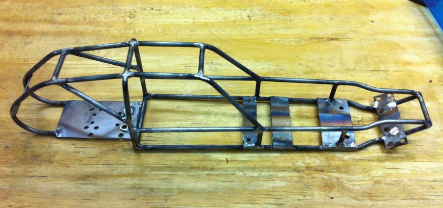
I have completed the first prototype of the tube chassis!
What an accomplishment. After over a year of drawing, thinking, building a shop, and finally welding something together I have learned that there is alot of work in something like this. I am planning to start on the first one for sale in the next week or two and will begin contacting those who emailed me wanting one. The price is not set yet, but will likely be about $199.


I tried to make a body without success. There are a few long edge bends that were nearly impossible with the lexan I bought. It was .040″ thick and takes alot of heat to soften. Unless I figure out a better way, there won’t be a custom body for this chassis. However, it looks like with one or two small changes to the chassis design, I should be able to fit the original body over the tubing. That would be cool!
So that’s it for right now. The first prototypes will be offered to the folks who have emailed me wanting them, and after that I will offer them on Ebay or in my Store. Want one? Let me know and I will put you on the list!